In March I wrote a couple of words about rotors which had cracks in blade groove.
The picture showed an example. Since that time these cracks have been removed.
It had not been easy to get rid off cracks located in such places like the egdes of blade groove. To do it, a special cutting tools were needed.
I am not a machining specialist but I have dealt with various machining issues and that is why I managed to create the cutting tools and proper machining technology to get rotors free of cracks.
Below, is a cut section of blade groove.
The shape in the edge 9 and 7 is what we got after machining. A lack of cracks was confirmed by NDE.
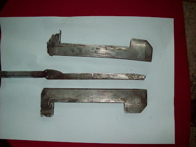
The cutting tools, we used :
The two pictures above show the tool used in first step of machining. To get shape from the first drawing the next tool was necessary
It is almost impossible to take pictures showing what is the blade groove geometry right now, anyway the machining path is visible and the rest is the same like on the drawing on the top of this post
poniedziałek, 24 maja 2010
wtorek, 6 kwietnia 2010
The calculation on rotor disc and the locking blade
It is not complicated to carry out this job but there are some steps critical which done improperly can cause disaster. Frankly speaking, reparing steam turbines, there is allways a must to think what would be the results of some "shorcuts".
That is why, the experience is very important. Especially, a blading work is one of the most sensitive. Take into account that the turbine rotor works in exceptional conditions: high temperature (~ 550 C deg), high pressure and forces created by elements weight, a rotor rotation (a couple of thousand rpm's), etc ... .
Anyway, the first stage consist of 52 blade sets, each set contains two blades welded together. Two sets are the locking sets. The locking sets are fixed to the disc using 4 pins. The core of reblading activity is to remove the pins. Usually, the pins are removed by boring them and here we have the most dangerous part of whole procedure. The pins boring have to be done in this way that the holes diameter in disc will be the same after boring - the holes clean up is acceptable but the diameter must not be bigger than certain value. A material thickness on the rotor disc in pins mounting area determines the pin holes diameters.
It can happen that after a few repairs of this rotor stage the pin holes are an ovals or were not bored perpendicular to the rotor disc.
Than it is technical correct to bore new holes but they will be bigger but as mentioned above holes can be increased only to some level as the stresses are important.
This conditions were met during a project supervised by me.
We had ovality on pin holes and some ot them were not perpendicular to the rotor disc.
I defined what would be the diameters of new holes and asked my colleague to perform stress calculation if disc material left is enough to carry forces.
He used FEA method to do it. I am not familiar with this but it is common for design dept. around the world.
Fortunatelly, it turned out that new holes diameters are ok and we act in this way.
Below, there are a couples of pictures presenting MES calculation.
środa, 17 marca 2010
IP rotor after fact finding activity
One of the IP rotor of two 150 MW units is in very bad condition.
The run- out measurement revealed the rotor curvature.
What we measured is showed on the chart above. The curve is the rotor's axis.
The rotor is bent and max run- out 0.23 mm is located behind 1 stage.
There are two most often applicable ways to get rid off curvature.
The first one is to machine the rotor and remove a "plus indications" so the rotor would be machined only at certain angle if material thickness to be removed was no more than 0.23 mm.
I have not seen such solution so far. The solution, we usually use is to define new rotor axis. In this particular case the new fix points sholud be a journal at IP-LP coupling and place when max run-out is measured. Next, the HP end of the rotor would be machined.
We have done such machinings but for the rotors which were not bent so much. At max indications ~ 0.15 mm. In fact the internal tensions are still present and can cause further axis deformation. We have noticed this process.
The right technical solution applied in this case is to perform thermal streightening and after this repair step to machine rotor.
The final decision will be taken shortly on the customer meeting.
The rotor curvature is not the only problem we found.
The rotor blade groove edges are cracked. Allways rotor cracks are very hard task to deal with.We have found different kinds of cracks.
1. The cracks inside the blade groove
2. The blade groove edges cracks.
czwartek, 11 lutego 2010
IP rotor reblading next steps
The inserts are removed, so the next step is to put out the blade which is in the middle. To do it it is necessary to move adjacent blades.
The teeth are on the both side of the locking blades, on the picture above only the convex blade side teeth are shown but on the concave blade side the teeth are present as well.
The insert was removed
The adjacent blades were moved clockwise and counterclockwise
and the middle blade is being released now
The middle blade/locking blade was removed
The middle/locking blade
The teeth are on the both side of the locking blades, on the picture above only the convex blade side teeth are shown but on the concave blade side the teeth are present as well.
When the middle/locking blade is out of the groove the next blades can be put out.
The set of locking blades is shown below. On the right hand side is the locking balde (the teeth are visible from both blde side). The blades with numbers are these ones which adhere to the locking blade form rigth and left hand side.
The locking set in removed, so just now the rest of the blades will be dissasembled. It takes some time as it has to be done piece by piece,
The rest stages were rebladed in exactly the same way.
niedziela, 10 stycznia 2010
IP rotor blades removal - 150 MW turbine
The scope of works for IP rotors includes the exchange of the blades. To do it, firstly the existing blades have to be disassembled. I would like to show a blades dissasembly process.
The pictures presents the locking insert, which we managed to put out with minimum damages.
The blades are put in on the rotor discs through a special prepared place. This "entry" is invisible before, but the dissasembly process starts exactly in this place.
The pictures shows a blades locking set . The locking inserts are marked, beetween them there are seven blades. The blade in the middle, marked with black dot is the locking blade.We have to put out the locking blade and then the rest is quite simple.
The very first step is to get rid off the shrouds. As the new blades with the additional hardware will be installed, there is on needs to be gentle - a hand grinder is used.
We have to reach the two locking inserts, that is why the locking blades and couples adjacent ones are cut off.
Just now there is convinient acces to the locking inserts, which are disassembled.
Each locking insert consists of three parts.
The pictures presents the locking insert, which we managed to put out with minimum damages.
The middle parts of the insert can be removed as a one piece but it is very hard to do and consumes a lot of time, so we safed only a very few samples and a rest were destroied during the removal works.
We make a hole in middle parts of the insert, so this was changed into chips. Below the insert is visible after the blade cut off.
The insert boring:
The insert boring:
niedziela, 3 stycznia 2010
150 MW turbines - continuation
Happy New Year to everyone who visits my blog ... .
I would like to specify what is the scope of work for the rotors, I mentioned in my previous post.
I think, that is a first approach and will be updated after fact finding activity we are doing since the middle of December , so here we have:
1. The HP rotors.
- blasting,
- NDT examination,
- measurement of the rotor's geometry,
- seal strips exchange,
- machining of a bearing journals, seal strips,
This is what I know for today but once any damages are revealed during NDT, the scope of work will be increased, certainly customer has to accept our proposals.
2. The IP rotors.
- blasting,
- NDT examination,
- measurement of the rotor's geometry,
- seal strips exchange,
- machining of a bearing journals, seal strips,
- all stages reblading
Similar remarks like above it had been defined before casings opening, so if customer agrees to accept an additional, necessary works, we will do it.
3. The LP rotors.
- blasting,
- NDT examination,
- measurement of the rotor's geometry,
- seal strips exchange,
- machining of a bearing journals, seal strips,
- reblading of L0 and L1 stages
Subskrybuj:
Posty (Atom)